

Solar Wastewater Treatment: Turning Toxic Hydrofluoric Acid into Clean Water

The paradox of the solar industry is rarely discussed. We champion photovoltaic (PV) panels as the saviors of the climate, silently converting sunlight into clean electrons without a smokestack in sight. However, the manufacturing of these green technologies has a dirty secret.
The production of solar cells—specifically the etching, doping, and cleaning stages—generates a toxic blend of wastewater that poses significant environmental threat. Without a robust Solar Industry Effluent Treatment Plant (ETP) , we aren’t just making energy; we’re creating a legacy of chemical pollution.
If you are a plant manager, an environmental consultant, or an EPC contractor working on a solar gigafactory, understanding the chemistry of this waste and the technology required to treat it is non-negotiable. This article dives deep into the hidden world of solar wastewater treatment and how modern Zero Liquid Discharge (ZLD) systems are solving the industry’s water pollution.
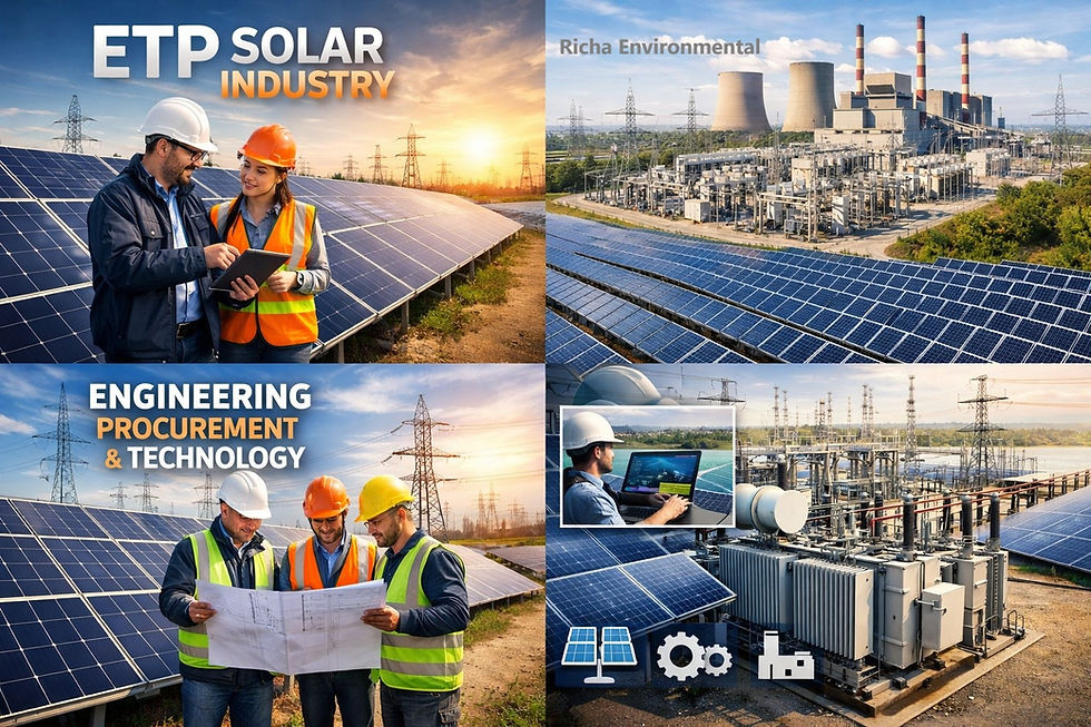
Solar Effluent
Standard industrial ETPs are not built for solar waste. The effluent from photovoltaic manufacturing is distinct because of the semiconductor materials involved. There are two primary waste streams, both equally dangerous:
1. The Silicon Ingot & Wafer Slicing Waste
Before a cell becomes a panel, bricks of crystalline silicon are sliced into ultra-thin wafers using a slurry containing silicon carbide and polyethylene glycol (PEG).
The Pollutant:This results in a high-strength organic load with suspended solids (silicon dust).
The Risk: If discharged, this fine dust can suffocate aquatic life and harden like cement in natural waterways.
2. The Cell Processing Waste (The Real Hazard)
This is where the effluent treatment complexity increases. To make the wafer function as a semiconductor, it undergoes texturing and etching using highly aggressive acids:
Hydrofluoric Acid (HF): Used to remove oxide layers. HF is known for being extremely toxic and capable of eating through human bone.
Nitric Acid (HNO3) & Phosphoric Acid: Used for doping and texturing, creating high nitrate and phosphate loads.
Heavy Metals: Silver and lead from solder and metallization pastes wash off the cells.
Result A low pH, acidic effluent with high Total Dissolved Solids (TDS) and fluoride concentrations that can decimate an ecosystem.
The Regulatory Landscape: ZLD is Now Mandatory
Gone are the days of deep-well injection or simple dilution. In most global manufacturing hubs, including India, regulatory bodies have classified solar effluent as hazardous waste, strictly mandating Zero Liquid Discharge (ZLD).
The logic is sound: fluoride and heavy metals cannot be effectively broken down by bacteria in a standard biological treatment plant. They accumulate, bio-magnify, and return to our drinking water. A modern Solar ETP is designed with absolute containment in mind—nothing liquid leaves the factory gate.
4-Stage Treatment Process: From Toxic Slurry to Reusable Water
Treating this effluent isn't just a single process; it’s a multi-barrier sequence designed to eliminate specific pollutants at every step.
Stage 1: Physico-Chemical Precipitation (Defluoridation)
Because the acidic pH (often 1-2) would corrode any downstream equipment, neutralization is step one.
Fluoride Removal: Lime (calcium hydroxide) is dosed into the effluent. It reacts with hydrofluoric acid to form insoluble calcium fluoride (CaF2) crystals.
Coagulation & Flocculation: Heavy metals and suspended solids are forced to clump together into a sludge, which settles at the bottom of a clarifier.
Output: Treated water with significantly reduced fluoride and heavy metals, plus a hazardous solid sludge cake from the filter press.
Stage 2: High-Efficiency Reverse Osmosis (HERO)
The overflow from the clarifier still contains dissolved salts and trace nitrates. A standard RO membrane would foul instantly due to the scaling potential.
The Process: The water passes through a multi-media filter and ultrafiltration (UF) to remove micro-solids, followed by a two-pass Reverse Osmosis system.
Function: The RO membranes separate clean water (permeate) from the concentrated brine.
Recovery Rate: A well-designed system can recover 70-85% of water, sending it back to the factory for non-potable uses like scrubber make-up or cooling towers.
Stage 3: The Brine Concentration
The 15-30% of water that remains is the "RO reject"—a high-TDS brine saturated with nitrates and residual fluorides. You cannot evaporate this thermally in a standard evaporator without massive energy costs. The solution?
Advanced Technology: Modern plants use High-Recovery Disc-Tube (DT) RO or Closed Circuit Reverse Osmosis (CCRO) to further squeeze the brine, taking recovery rates up to 95-98% before heat is applied.
Stage 4: Thermal Zero Liquid Discharge
For the final 2-5% reject:
Multiple Effect Evaporator (MEE) & Agitated Thin Film Dryer (ATFD): The concentrated brine is boiled under vacuum. Water vapor is condensed and recovered, while the residual salts form a thick slurry.
The End Product: The ATFD turns the slurry into a bone-dry mixed salt powder, which is disposed of in a secured hazardous landfill. No liquid discharge.
The Hidden Pain Point: Silica Scaling and HF Corrosion
If you are designing an ETP for a solar plant, your biggest operational nightmare isn't the CAPEX—it's the OPEX caused by scaling.
The PV industry uses sodium silicate as a thickening agent. Silica combines with the lime in Stage 1 to form a cement-like scale that blocks pipes and RO membranes within days. A truly optimized Solar ETP requires a high-pH de-silication step upstream, often using proprietary chemical dosing to lock silica in a fluidized bed reactor before it hits the main treatment line.
Furthermore, material selection is critical. Residual fluoride is a predator to stainless steel. All piping, pumps, and gaskets in the pre-RO stage should be high-grade PP/FRP or PTFE-lined to prevent pin-hole leaks that can turn catastrophic.
Looking for a Tailor-Made Solar ETP Solution?
Navigating the complexities of fluoride removal and high-purity water recycling requires a specialist engineering partner. Richa Environmental Services Pvt Ltd designs future-ready, fully automated ZLD plants specifically for the photovoltaic and semiconductor sectors.
Contact us today for a process guarantee.
Keywords: #Fluoride removal from solar #wastewater, #Solar industry #effluent treatment plant, Photovoltaic wastewater treatment,

Comments